Difference between revisions of "User:Heritagefutures/WorkSpace3"
(→Beck) |
(→WRE) |
||
| Line 61: | Line 61: | ||
[[Category:Aerial cameras]] | [[Category:Aerial cameras]] | ||
[[Category:Military cameras]] | [[Category:Military cameras]] | ||
| − | |||
| − | |||
| − | |||
| − | |||
| − | |||
| − | |||
| − | |||
| − | |||
| − | |||
| − | |||
| − | |||
| − | |||
| − | |||
| − | |||
| − | |||
| − | |||
| − | |||
| − | |||
| − | |||
| − | |||
| − | |||
| − | |||
| − | |||
| − | |||
| − | |||
| − | |||
| − | |||
| − | |||
| − | |||
| − | |||
| − | |||
| − | |||
| − | |||
| − | |||
| − | |||
| − | |||
| − | |||
| − | |||
| − | |||
| − | |||
| − | |||
| − | |||
| − | |||
| − | |||
| − | |||
| − | |||
==WRETAR== | ==WRETAR== | ||
Revision as of 05:00, 30 October 2012
Contents
Missile Stuff
Missile Cameras
Cameras played a major role in documenting the experiments and testing carried out the early days of guided weapons development. A suite of specialised cameras were developed in the mid- to late 1950s by various U.S. manufacturers, by Soviet camera makers and by the Royal Aircraft Establishment in the UK.
In Australia, the Weapons Research Establishment (South Australia) designed such cameras as part of the Anglo-Australian Joint Project (1946 to 1980) which focussed on guided weapons and missile development. The research focussed on a missile's behaviour in flight relying on observation and general telemetry data. While the latter would be displayed on an cathode-ray oscilloscope in real time, they needed recording to allow for detailed analysis. Film was a suitable medium to record such transitory analog data. To this end, high-speed cine cameras were developed which capable of 100 frames/second and more. While recorded data would be viewed as segments of motion film many were analysed on a frame-by-frame basis.
In principle, cameras were developed for four different applications: ground-based cameras for observation and the recording of the telemetry, and airborne cameras, either borne by the missile or carried by the target.
Ground based cameras
Missile behaviour
- Telemetry recording
Recording of moving Oscillograph data occurred principally with the GW 3 camera. Such cameras also existed in the civilian arena (such as the Cossor 1428).[1]
Airborne cameras
Missile-borne cameras
Target Aircraft Cameras
Notes
- ↑ The Fairchild F-296 is an example of camera used to record stable oscillograph data where a single image sufficed for the purposes documentation.
| FEEL FREE TO LOOK, BUT PLEASE DO NOT TOUCH... |
GW cameras
|
| Dekko GW 1 Mk 1A image by Dirk HR Spennemann (Image rights) |
During the early period of the Cold War the United Kingdom carried out wide-ranging missile research, partly in collaboration with Australia (under the umbrella of the Anglo-Australian Joint Project, which ran from 1946 to 1980). [1] The testing of the missiles required a range of sophisticated devices to record and document missile behaviour in flight, approaches to targets and also to record telemetry data that were obtained on the ground. In the days prior to digital data collection this occurred analog, with film being the preferred option. All cameras carry the type specification GW for Guided Weapons. While technically most of the cameras where high speed cine cameras (100 frames/second), many of them were used for frame-by-frame analysis:
- GW 1 Target Aircraft Camera (Dekko Ltd, 1954)-- a high-speed 35mm cine camera mounted in the target aircraft to record the missile approach angles (and miss distances).
- GW 2 Target Aircraft Camera (Beck, 1955)-- a high-speed 35mm cine camera mounted in the target aircraft to record the missile approach angles (and miss distances).
- GW 3 Continuous Record Camera (Cinetra Ltd, 1958). The GW3 was a high-speed 35mm cine camera developed to record cathode ray oscillograph images at various speeds.[2]
- GW 9 Missile Camera (Specto Ltd, 1960)—A 16mm high-speed cine camera with interchangeable lenses, carried by missiles in flight.[3]
In Australia a number of similar cameras were built which carried different designations: WRECISS, WREROC and WRETAR.
Notes
- ↑ For background on the project see Morton, Peter (1989) Fire across the desert. Woomera and the Anglo-Australian Joint Project 1946–1980. Canberra: AGPS.—For general context of UK guided weapons development in the 1950s see Twigge, S.R. (1993) The early development of guided weapons in the United Kingdom, 1940-1960. London: Routledge.—For Woomera see also: Southall, Ivan (1962) Woomera. Sydney: Angus & Robertson.
- ↑ The camera was jointly developed by the Royal Aircraft Establishment and Cinetra Ltd. It took 200ft rolls of daylight loadable 35mm cine film. The design had a geared advance that allowed for recording speeds of 1 inch/sec to 128 inches/sec. The camera came with three interchangeable lenses (1 ¼", 2" and 3") all with f/1.9. A time marker unit was also fitted.-- For details and specifications, see: Brooks, J.H. (1958) Type GW 3 continuous record camera. (UK National Archives AVIA 6/23834).
- ↑ The 16mm camera, running at 100 frames/sec, was designed and built by Specto Ltd, (London. Specto were manufacturers of cine cameras and projectors, operating from 1935 to 1960 (list of manufacturers of vintage cinematographic equipment). --The GW 9 came with four Specto Ltd. lenses (1/2” f/4; ¾, f/4.5; 1 ½”, f/1.9 and 3’, f4). In addition, it could accept lenses designed for the G.S.A.P. cameras. The camera used a circular disc shutter with two sectors cut out of the rim. At 100 frames/sec the shutter speed was 1/210th. The 50ft of daylight loadable 16mm film allowed for 20 seconds of running time.--For details and specifications, see: Husbands, C.W. (1960) The type GW 9 missile camera. Royal Aircraft Establishment Technical Note TD47, March 1960. London: Royal Aircraft Establishment (Farnborough), Ministry of Aviation (UK National Archives AVIA 6/23847).
WRETAR
|
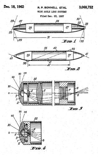
| Patent Application for the Dixon Ultra Wide Angle Lens US Pat. Nº 3068752 image by U.S. Patent Office (Image rights) |
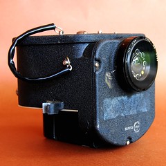
The WRE Target Aircraft Recorder (WRETAR) is one of a suite of specialised cameras developed in the mid- to late 1950s the Weapons Research Establishment (South Australia) in conjunction with the Anglo-British guided weapons development. The WRETAR is as a more compact and light weight alternative to the Dekko GW 1 and Beck GW 2 target aircraft cameras.
While technically a high speed cine camera, shooting at 100 frames/second, the resulting negatives were not projected as a film but examined individually in order to assess the miss distance of the missile in relation to its target.
In 1955-56, the Australian Government Aircraft Factories (GAF), in collaboration with Australia’s Weapon Research Establishment (WRE), developed a newly designed ultra-wide lens with 210º coverage.[1] When fitted to a newly designed 35mm film camera capable of 100 frames / second (WRETAR), the lens yielded a coverage of 186º. Thus one unit could cover a full hemisphere. The smaller lens allowed for much more compact design of the wingtip camera recorders, reducing the number of cameras required in each pod from 5 to 2 and thus reducing overall weight by 70lb.[2] The camera was ready for prototype production in March 1956.[3] Two design options had been developed for the camera, a short back-focus version and a more slender long back-focus one. The first option was the preferred version and entered service in 1957.[4][5] The whole sky could be covered with two units in the standard wing-pod configuration, with one camera mounted looking up and the other one looking down.[6] This required only small blisters to protrude from the pods. WRETAR was capable of ‘recognising’ a missile within 250ft of the camera (larger missiles at a greater distance). [5]
The film magazine took a standard 50ft roll of 35mm cine film, which gave the camera a run time of 12 seconds.[7]. Variant models of the camera used 100 foot daylight loadable rolls of 35mm film on a thinner base, which allowed for 24 seconds run time (or to record two trials at 12 sec each).[7][8]
A number of WRETAR versions were produced with varied advance speeds, exposure times and apertures:[9]
- WRETAR Mk 1 is capable of 100 frames /second at 1 milli-second exposure with an aperture of F/8 (when fitted with a minus bluefilter).[7] A roll of 35mm film gives a maximum running time of 20 seconds.[9]
- WRETAR Mk 2 Listed but no details known. Additional versions with altered advance speeds (up to 160 frames/second,[7]had been developed.
- WRETAR Mk 3 Listed but no details known.[10]
Notes
- ↑ Dixon, F.A. (1961) Cameras with Wide Fields of view used in Rocket Research at the Woomera Range, South Australia. In: K.J. Habell (ed.), Proceedings of the Conference on Optical Instruments and Techniques London 1961. New York: John Wiley & Sons. Pp.273-278.—‘Wide Angle Lens Systems.’ US Patent Filed 23 Dec 1957; Issued 18 Dec 1962. Applicants: Robert P. Bonnell, Jack V. Ramsey and Robert A Dillon, assigned to The Commonwealth of Australia. US Pat. Nº 3068752.—This was a major development for the Australian optics industry: Steel, W. H. (1964) Optics in Australia. Applied Optics vol. 3, nº 7, pp. 839-842.
- ↑ A.M.P.O.R. for Target Aircraft. Memorandum N.W.Hodgson, Manager GAF, Fishermen's Bend, to Controller WRE, Salisbury. Dated 3 November 1955. Contained in File: "Incorporation of Modifications AMPOR Cameras Mk 1A.' Australian Archives A705 File 165/2/80.
- ↑ Proposed improved AMPOR Instrumentation System. R.P. Bonnell, P.O. Optics and Servomechanisms to Superintendent Techniques, dated 19 March 1956 file nº SA 5270/2 SOA 117. Contained in File: "Incorporation of Modifications AMPOR Cameras Mk 1A.' Australian Archives A705 File 165/2/809.
- ↑ The first production run was 192 units (DSTO Timeline 1946 - 2007).—In the U.K. the WRETAR was called WRE Mk. 1
- ↑ 5.0 5.1 Evans, J.B. (1963) Analysis of records obtained from target aircraft camera systems. Royal Aircraft Establishment Technical Note IR 32, November 1963. London: Royal Aircraft Establishment (Farnborough), Ministry of Supply (UK National Archives AVIA 6/25551).
- ↑ Frost, J.M.R. & Morton, P. (1988) Instrumentation at the Woomera Rocket Range. Australian Journal of Instrumentation and Control vol. 3 nº 3, pp. 18-20.
- ↑ 7.0 7.1 7.2 7.3 Wood, J. (1962) Wide Angle Lens Instrumentation. Missile. Quarterly Magazine for the Members of the Weapons Research Establishment Institute vol. 8 nº 1, pp. 4-6,
- ↑ Royal Aircraft Establishment (1968) Air Targets at the R.A.E. Aberporth Range. Air Targets Issue 3, November 1968. AVIA 6/23916. Royal Aircraft Establishment (Ranges Division).
- ↑ 9.0 9.1 Anon (1963) This is Fairey: Fairey Aviation Company of Australasia Pty Ltd. Fairey Review, vol. 5 nº 3, p. 39-43.
- ↑ Smith, A. T. (1973) Miss Distance Measurement Using One Camera. Royal Aircraft Establishment Technical Report 73162 (9 October 1973). London: Royal Aircraft Establishment (Farnborough), Ministry of Defence.
| FEEL FREE TO LOOK, BUT PLEASE DO NOT TOUCH... |
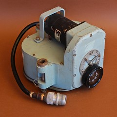
WREROC
|
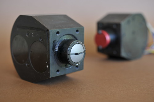
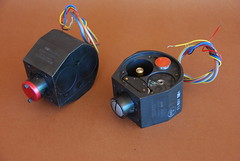
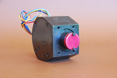
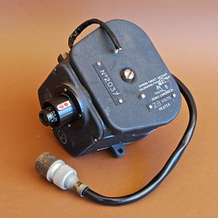
| WREROC Mk II Missile Camera image by Dirk HR Spennemann (Image rights) |
The Weapons Research Establishment Roll Orientation Camera (WREROC) is one of a suite of specialised cameras developed in the mid- to late 1950s the Weapons Research Establishment (South Australia) in conjunction with the Anglo-British guided weapons development. WREROC was developed to record the roll (rotation) of a missile in flight in relation to the horizon. It drew on the Dixon lens developed for WRETAR cameras.[1]
Background
One of the major challenges encountered when testing missiles in the 1950s and early 1960s was to determine the amount and angle of roll during the flight. Some missiles intentionally used roll as a part of their stabilisation, while others developed roll during experiments. Ground observations were not always possible or accurate and in-flight telemetry was still in its infancy. To document the nature and speed of missile roll, WRE developed a unique camera, the WREROC (WRE Roll Orientation Camera). It drew on the ultra wide lens[2] also used in WRETAR[3] and WRECISS[3][4][5] The camera had to be designed very small and compact to fit into the missile, but also robust enough to withstand ground impact for those occasions where the missile crashed accidentally or where the standard parachute recovery was not used.[3].
|
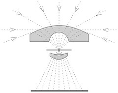
| Lens Diagram of the Dixon Ultra Wide Angle Lens image by Dirk HR Spennemann (Image rights) |
Description
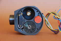
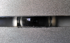
The extreme 186° fish-eye angle of the lens was restricted to a narrow slit of 2 mm width. The 35mm film was moved at a constant speed past the slit and was exposed at f/8 with an exposure time of 2 milliseconds. The camera had the capacity of 15 foot roll of colour film, which gave a total exposure time of 3 minutes. A time base was recorded at the film’s edge and three stadia lines were imprinted on the film.[3] While technically a WREROC is a high speed cine camera, the resulting film was not projected as a movie. Rather, the resulting negative is a continual strip that shows the horizon throughout the duration of the flight. Two cameras were installed in the missile at right angles to the roll axis, pointing in opposite directions. This dual installation provided instrumentation redundancy, but also removed ambiguity in situations where the white glare coming of salt lakes could be confused with the sky just above the horizon.[3]
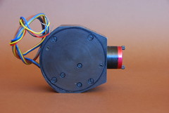
The camera measures 7 x 8 x 5 cm (3 x 3 5/8 x 2 inches) and weighs 1.32kg (2.9 lb) ! It has been milled from a single piece of steel. Access to the internal mechanism (film advance, shutters, electro motor, diodes for time-base), as well as loading the unit with film, is achieved by two solid side plates that are securely bolted down in recessed (flush with the body).
|
|
| ||||||
|
|
| ||||||
|
A Weapons Research Establishment Roll Orientation Camera (WREROC) | ||||||||
Sample Images
Links
- Spennemann, Dirk HR (2012) History, Description and Technical Details of the WREROC missile cameras. vers. 1.0 {: CAMERA | TOPIA :} ¶¶
Notes
- ↑ For an in-depth description, see Spennemann, Dirk HR (2012) History, Description and Technical Details of the WREROC missile cameras. vers. 1.0 {: CAMERA | TOPIA :} ¶¶
- ↑ Wide Angle Lens Systems.’ US Patent Filed 23 Dec 1957; Issued 18 Dec 1962. Applicants: Robert P. Bonnell, Jack V. Ramsey and Robert A Dillon, assigned to The Commonwealth of Australia. US Pat. Nº 3068752
- ↑ 3.0 3.1 3.2 3.3 3.4 Dixon, F.A. (1961) Cameras with Wide Fields of view used in Rocket Research at the Woomera Range, South Australia. In: K.J. Habell (ed.), Proceedings of the Conference on Optical Instruments and Techniques London 1961. New York: John Wiley & Sons. Pp.273-278.
- ↑ WRECISS—Weapons Research Establishment Camera Interception Single-Shot
- ↑ ‘Midget Camera for Guided Missiles.’ The Photographic Journal vol. 100, 1960, 173.—‘Midget Camera for Guided Missiles.’ Industrial and Commercial Photographer vol. 1, nº 2, 1960 p. 40.—‘Midget Camera for Guided Missiles.’ Aircraft Engineering vol. 32, 1960, p. 119.—‘Midget Camera for Guided Missiles.’ Military Review vol. 40, nº 1, 1960, p. 78.—‘Camera measures missile accuracy.’ Missiles and Rockets vol. 6, 1960, p. 32.—Beharrell, B | Collier, M J (1966) Photogrammetric methods applied to WRECISS computation (Photogrammetric methods applied to calculation of target position and attitude relative to missile). WRE Technical Note TRD-22, 16pp. Salisbury (Australia): Weapons Research Establishment, Dept. of Supply
| FEEL FREE TO LOOK, BUT PLEASE DO NOT TOUCH... |
Beck
- Asymmetrical Lens clean mine!
Beck Sky Camera
British pat n°225 398/1923
Focal length near 1 inch (2.5cm) and image circle is approximately 3 inch (7.5cm)
For circular images 2½ in. dia. on 3¼ x 4¼ in.plates, English, c. 1924, the mahogany box-form body with fixed focus brassbound R&J Beck 180 'fish-eye' ƒ8 lens with three built-in filters, and one block-form double plate holder.
Designed and patented by Robin Hill of the Biochemical Laboratory, Cambridge in 1923, British Pat. No.31931/23, for photographing cloud formations. The distortion produced by the lens was corrected by using the same lens again for projection of the image. It was used by the Meteorological Office for many years. Original price £18/18/0.
Literature: R. Hill, Quarterly  Journal of the Royal Meteorological Society. Vol.50 (1924) p.227-23;  Dr.H.v. Socher, Optik Mit 180 Gesichtsfeld, Das Deutsche Lichtbild, 1931.
Camera has built-in shutter. Speeds are: 1/100, 1/50, 1/25, 1/10, 1/5, 1/2, 1sec, B and T. Lens has built-in yellow filter. Apertures are 8, 11, 16, 22 and 32
Beck Guided Weapons Lenses
|
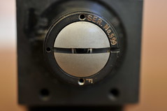
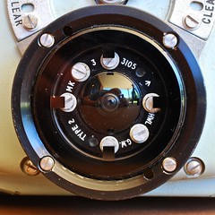
| R&J Beck designed G.W. Type 2 Mk.3 lens image by Dirk HR Spennemann (Image rights) |
The folowing lenses have been documented
- GW Type 2 Mk 2 (on a Dekko GW 1 Mk1A)
- The lens is
- GW Type 2 Mk 3 (on a Dekko GW 1 Mk1A and a Beck GW 2)
- The lens is similar to the Type 2 M2, but is surrounded by four diodes for @@@
- GW Type 3 Mk 2 (on a Dekko GW 1 Mk1C)
| FEEL FREE TO LOOK, BUT PLEASE DO NOT TOUCH... |
| Military Cameras |
|---|
| Aerial Cameras | XXX | Fairchild F8 | Fairchild K-17 | XXX | XXX | XXX | XXX | Solar-Vought Torpedo Camera | |
| | Konishiroku GSK-99 | | XXX | XXX | XXX | XXX | XXX | XXX | |
| Combat Cameras | XXX | XXX | Simmon PH-501/PF | XXX | XXX | XXX | XXX | XXX | |
| Gun Cameras | XXX | XXX | XXX | XXX | XXX | XXX | XXX | XXX | |
| Missile Cameras | WRECISS | WREROC | WRETAR | XXX | XXX | XXX | XXX | XXX | |
| FEEL FREE TO LOOK, BUT PLEASE DO NOT TOUCH... |
| FEEL FREE TO LOOK, BUT PLEASE DO NOT TOUCH... |
Dekko
Between the 1930s and 1950s Dekko Cameras Ltd[1] produced a range of cine cameras for civilian application[2] In addition, Dekko produced a range of projectors for 8mm, 9.5mm and 16mm format.[3]

|
| Dekko 128 image by John Burke (Image rights) |
Civilian Cameras
- Dekko 104 DeLuxe (1935)—a bakelite 9.5mm camera, 8-64 fps, could shoot stills (1.45 kg, 59x125x150 mm) on record with:
- Dekko 110 (1947)—a metal 8mm camera fitted with National Optic Anastigmat f/2.5 12.5mm
- Dekko 128 (1950)—a 8mm camera (0.9 kg, 63x127x127 mm) with National Optic Anastigmat f/2.5 12.5mm
????
|
| Dekko GW 1 Mk1C Aircraft Target Camera fitted with R & J Beck GW Type 3 Mk2 lens image by Dirk HR Spennemann (Image rights) |
Military Cameras
During World War II the company had also designed the Dekko type N model 136 (1940) aircraft magazine camera. After World War II it was approached by the Royal Air Force to develop a high speed camera to record missile strikes on target aircraft (the Dekko GW 1).[8] Even though the latter was technically a high speed cine camera, shooting at 100 frames/second, the resulting negatives were not projected as a film but examined individually in order to assess the miss distance of the missile in relation to its target.
It seems that Dekko withdrew from the civilian movie camera market in the late 1950s and expanded into the business of electronics instrumentation[9]. High speed cameras for research and instrumentation purposes continued to be produced,[10] as were adaptations of movie cameras to single shot devices for data recording of experiments[11].
Links
- ¶¶ Spennemann, Dirk HR (2012) History, Description and Technical Details of the GW Target Aircraft Cameras. vers. 1.0 {: CAMERA | TOPIA :}
- 9.5 mm equipment catalogue
- 9.5mm cameras (Anna & Terry Vacini Binocular and Cine Collection
Notes
- ↑ Addresses:1934-1938: Slough, Buckinghamshire; 1938-1950s: Telford Way, East Acton, London, W3, UK
- ↑ For patents held by Dekko see: Perfectionnements aux chargeurs de film pour caméras. Inventors Alan Percy Smith and Henry Arthur Bence-Trower. Applicant Dekko Cameras Ltd. Application date 25 August 1938. Publication date 14 June 1939. French Patent nº FR 842562 (A).—Improvements in or relating to cinematograph projectors. Inventors Dekko Cameras Ltd. and Frederick Wheeler Stanley. Applicant Dekko Cameras Ltd. Application date 28 February 1948; Publication date 6 January 1952. British patent nº GB 665136 (A).
- ↑ Dekko 1 (1937?), 9.5mm projector with crank 60 ft reels 40V. 15W; Dekko 2 (1937?), 9.5mm projector with motor 60 ft reels 40V. 15W; Dekko 3 (1939), 9.5mm projector with crank 50V 25W; Dekko 4 (1939), 9.5mm projector with motor 50V. 25W; Dekko 5 (1939), 9.5mm projector 400 ft; Dekko 6 (1939), 9.5mm projector 400 ft; Dekko 7 (1939), 9.5mm projector 400 ft; Dekko 8 (1939), 9.5mm projector 400 ft; Dekko 48 (1939), 9.5mm projector 100/115V. 50 W. 400 ft.; Dekko 118a (1947), 8mm projector 500 W; Dekko 118b (1947), 8mm projector 500 W; Dekko 118c (1947), 8mm projector 500 W; Dekko 119a (1947), 9.5mm projector 110V. 500 W.; Dekko 119b (1947), 9.5mm projector 110V. 500W; Dekko 119c (1947), 9.5mm projector 110V. 750W; Dekko 126A (1949), 16mm projector 500W; Dekko 126B (1949), 16mm projector 500W; Dekko 126C (1949), 16mm projector 500W.—See also: Dekko Cameras Ltd. (1952) Projector for 16 mm cinematograph films. Journal of Scientific Instruments vol. 29 nº 2, pp. 62-63.
- ↑ 4.0 4.1 4.2 4.3 4.4 4.5 4.6 4.7 9.5mm cameras (Anna & Terry Vacini Binocular and Cine Collection).
- ↑ Advertisement The Straits Times, 4 April 1935, Page 1 Column 2.
- ↑ National Media Museum / Science & Society
- ↑ Lens only, has three holes on flange, one section of flange is a straight cut: Ebay 110729130708 (August 2011)
- ↑ Spennemann, Dirk HR (2012) History, Description and Technical Details of the GW Target Aircraft Cameras. vers. 1.0 {: CAMERA | TOPIA :}
- ↑ ‘The Industry’ ‘’Flight’’ 29 July 1957, p. 145
- ↑ Coleman, K R (1967) Some recent work on the photography of transient events. ‘’Journal of Scientific Instruments’’ vol 44 nº 5, pp. 321
- ↑ Howell, R.S (1963) The Flight Recorder. Appendix 2 to: W.F. Fielding, Kinetic and solar heating of 1000lb bombs examined at R.A.F. Idris, August-September 1962. Technical Note WE 13. Farnborough: Royal Aircraft Establishment. Page 16
| FEEL FREE TO LOOK, BUT PLEASE DO NOT TOUCH... |
Dekko GW 1
| Heritagefutures/WorkSpace3 |
|---|
|
Manufacturer: Dekko Cameras Ltd
Film type: 35mm
|
Background
While technically a high speed cine camera, shooting at 100 frames/second, the resulting negatives were not projected as a film but examined individually in order to assess the miss distance of the missile in relation to its target. The film magazine took a standard 50ft roll of 35mm cine film, which gave the camera a run time of 12 seconds.
|
|
| Dekko GW 1 Mk 1A image by Dirk HR Spennemann (Image rights) |
Technical designs
Mk 1A
Mk 1B
The existence of a Mark 1B camera can be inferred but units of this type have not been available for examination at the time of writing.
Mk 1C
Mk 1D
The identification data engraved on the cover for the film magazine-loading bay read the same as those documented for the Mark 1C, with the exception that the text Mk 1C’ has been replaced by ‘Mk 1D.’ The sole Mk 1D unit examined carried a R&J Beck GW Type 3 lens. There is no readily visible difference between the Mk1C and Mk1D models, either in overall appearance, lenses or mechanics.
Links
- ¶¶ Spennemann, Dirk HR (2012) History, Description and Technical Details of the GW Target Aircraft Cameras. vers. 1.0 {: CAMERA | TOPIA :}
Notes
| FEEL FREE TO LOOK, BUT PLEASE DO NOT TOUCH... |
Beck GW 2
| Heritagefutures/WorkSpace3 |
|---|
|
Manufacturer: Dekko Cameras Ltd
Film type: 35mm
|
Background
While technically a high speed cine camera, shooting at 100 frames/second, the resulting negatives were not projected as a film but examined individually in order to assess the miss distance of the missile in relation to its target. The film magazine took a 100 foot roll, which gave the camera a run time of 12 seconds.
Technical designs
Links
- ¶¶ Spennemann, Dirk HR (2012) History, Description and Technical Details of the GW Target Aircraft Cameras. vers. 1.0 {: CAMERA | TOPIA :}
Notes