Agfa Optima Rapid 125C
|
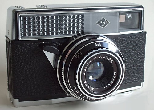
| Optima Rapid 250 image by photog 70 (Image rights) |
The Agfa Optima Rapid 125C is German made 35mm camera utilizing the Agfa Rapid 35mm film cartridges. Introduced in 1967 [1], it is part of the Agfa Optima series of Agfa cameras from the latter 1960s. The Optima Rapid 125C camera is an automatic exposure camera, with a selenium cell exposure meter coupled to the aperture and film cartridge ASA sensing tab. The camera has the same boxy form like the ISO cameras, but is a slightly larger. It is also heavier than the Agfa Iso-Rapid C cameras, having more metal parts, a film advance lever, and a better lens. The lens is a F2.8 /35mm Color-Apotar with settings somewhat similar to those used on the Agfa ISOMAT Rapid C camera. The "C" denotes that this camera uses flashcubes.
Overview
The camera body of the Optima 125C is still made of similar black plastic as used in the ISO cameras, but the top cover, shutter button, bottom cover, front chromed surround, and film door are made from metal. The most notable difference of the Optima 125C is the film advance lever which is on the bottom of the camera, left side, and is designed to be operated by the left hand, vs the right handed thumb-wheel of the ISO cameras. The film counter is on the bottom of the camera also. The top of the camera has only the shutter button, which contains threading for a cable release, and the recessed flashcube mounting. The viewfinder is in the same location as on the ISO cameras, but has glass lenses and has etched frame guidelines. On the right side of the viewfinder when looking through the viewfinder, a red dot can be seen with sufficient ambient light. This dot changes to green when there is sufficient light for an exposure, and the shutter is partially depressed.
The back of the camera contains an exposure guide table, three rows for 3-DIN/ASA ranges of film by row; 15...17 (25..40), 18....20 (50...80), and 21...23 (100...160), then 5 columns of distances, 1.5m (5 ft), a symbol of 2 people waist up, 3m (10 ft), a symbol of a 3 person family, and 5m (16 ft). This exposure guide is also the cover for the flash battery compartment. It is removed by lifting the left edge of the guide with a fingernail.
These cameras have a serial number on the left edge of the camera, next to the film door hinge. The serial number is in the form of " AG 6825 AM".
Details of operation
The back of the camera is opened the same way the ISO cameras are, by sliding the small silver triangle latch on the right side downward, and the back swings open to the left. The inside visually looks like the inside of the ISO cameras, but it is different, specifically because the film moves from the "new or full" cartridge which is in the left side of the camera, right to the "empty" cartridge on the right side of the camera. This is the reverse direction of the ISO cameras and is likely due to the positioning of the film advance lever on the bottom left side of the camera. The full and empty Rapid film cartridges are held in place by spring fingers similar to other Rapid film cameras.
The ASA tab of the Rapid film cartridge pushes on the center tab between the cartridge spring fingers of the left side of the rear interior of the camera. This center tab mechanically senses the length of the tab, and thus the ASA of the cassette, e.g. the film. This tab interacts with the metering system to adjust the aperture of the lens based on the film speed and available light. Similar to the ISO cameras, there is a rear door sensing tab and a film sensing tab. These are in different locations from the ISO cameras. The rear door open/closed sensing tab (silver) is in the bottom rear door channel of the camera slightly to the right or center. The film sensing tab is also silver and located just below the lower film drive gear, and senses when film is present in the camera.
With no film in the camera and the rear door open the film advance lever operates freely without stopping, turning the film drive gears. The camera shutter does not work. The film counter remains on "A". This mode of operation does not change if you depress the film sensing tab. With no film in the camera and the rear door closed,the film advance lever operates freely without stopping, turning the film drive gears. The camera shutter does not work. The Film counter remains on "A". With a fresh Rapid cassette of film in the camera, the film advance lever advances two full strokes and then stops. The film counter is on 16. The camera is ready to take a picture. After the shutter is fired, the film advance lever advances the film one frame and then stops. The camera then operates normally taking pictures at each frame. When the #1 picture (the last frame) has been taken the film advance lever operates without stopping and the shutter button does not work. Several strokes are require to advance the film to its end.
The lens of the Optima 125c has a black plastic ring at the base of the lens next to the camera body. This black ring rotates to several positions as indicated by a white triangle. Rotating the ring to align the triangle with the furthest left mark "B" (in black) which is bulb, the shutter stays open as long as the shutter button is depressed, and the shutter closes when the shutter button is released. To the right of the black "B" is a red "A", which indicates Automatic mode. In this mode the camera determines the correct aperture to use based on the available light as measured by the selenium cell meter. Turning the black plastic ring right-ward from "A" into the flash marked area, the camera must be turned over and a second white triangle is seen on the black plastic ring, opposite the aperture numbers; 2.8, 4, 5.6, 8, 11, 16, and 22. For operation with a flash, the aperture must be set for the subject distance vs flash guide number. The aperture is behind the shutter and can not be seen looking into the front of the lens, but can be seen by looking at it from the open back of the camera.
Hot Shoe Adapter
The recessed flashcube mounting can also use a plastic hot shoe adapter which slides into place over the flashcube mount. The plastic adapter has a ground contact on the right side of the foot, and single metal dot on the bottom, which match with contacts on the camera body. . These contacts contact similar contacts on the 125C camera and trigger a flash unit via a PC cord from the PC socket in the adapter.
Disassembly notes
The top cover plate is easily removed by removing the three Phillips head wood type screws visible in the top plate.
The front chrome metal rim of the camera can be removed by undoing 4 black flat head slot drive screws which can be seen in each corner, INSIDE the back of the camera. The front clear plastic cover and aluminum label plate fall out when the front metal ring is removed.
The bottom cover is more difficult to remove, as the film advance lever must first be removed. It has a center "screw" similar to those seen on the top film advance levers of 35mm rangefinder and SLR cameras. This screw has 2 pin dimples for a pin type wrench. It is not clear which direction this center plate turns to loosen. Logically it would be a left hand tightening thread, so that advancing the film would also tend to tighten the screw. BUT THIS IS NOT CONFIRMED!, so be gentile if you attempt to remove the film advance lever retaining screw. Too much force in the wrong direction could shear off the brass threads of the screw. After the film advance lever is removed three Phillips pan head wood type screws can be removed and the plastic bottom cover should come off. (haven't done that yet).
The film door latch and its cover plate would seem to be held in place by the bottom cover, as there are no screws holding the cover plate to the camera body as used on the ISO type cameras.
The lens has no visible screws on its exterior to indicate how it is disassembled. In the interior of the camera, in the light path area on the back side of the lens are 4 black flat slot head screws. If these are removed the lens assembly can be pulled partially away from the camera body. It is however limited by the flash trigger wiring between the camera body and the shutter in the lens. Successful removal of the lens from the camera would require de-soldering the 2 wires from their attachment locations inside the camera body at the flashcube mount or battery. NOTE: the rectangular front metal body ring and front body parts must be removed first to remove the lens.